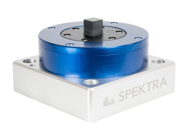
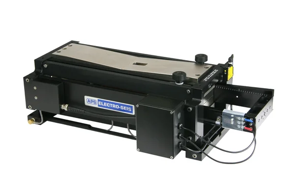
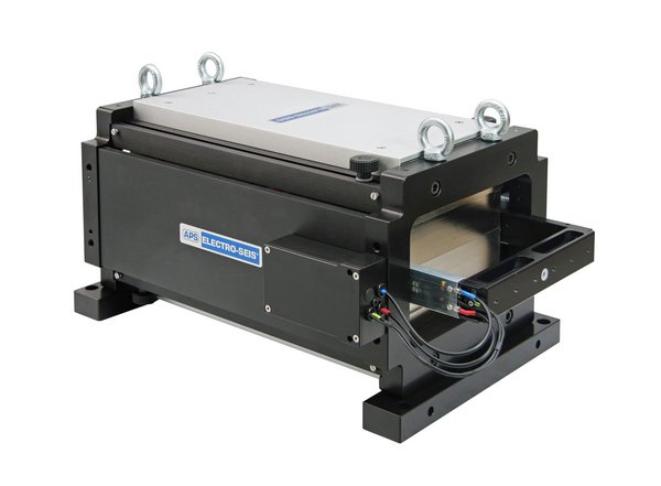
APS 113
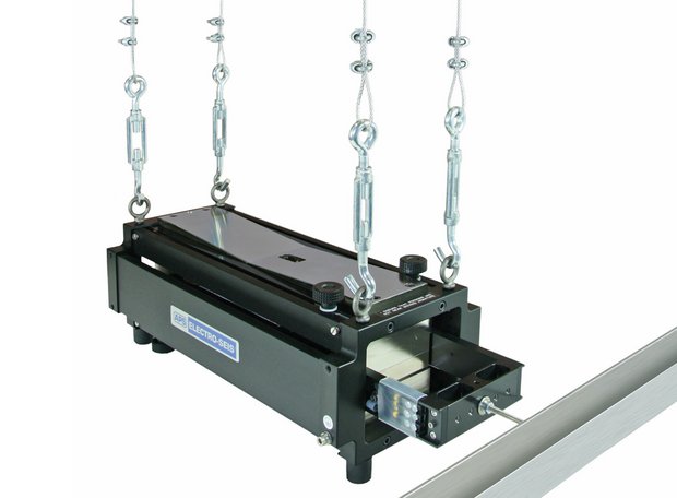
ELECTRO-SEIS® modal shaker specifically designed to be used alone or in arrays for modal excitation of complex structures, particularly at low frequencies.
Different operating modes with reaction masses, fixing points or auxiliary table kits multiply the application possibilities.
APPLICATIONS
What are the SPEKTRA areas of application?
Learn more …
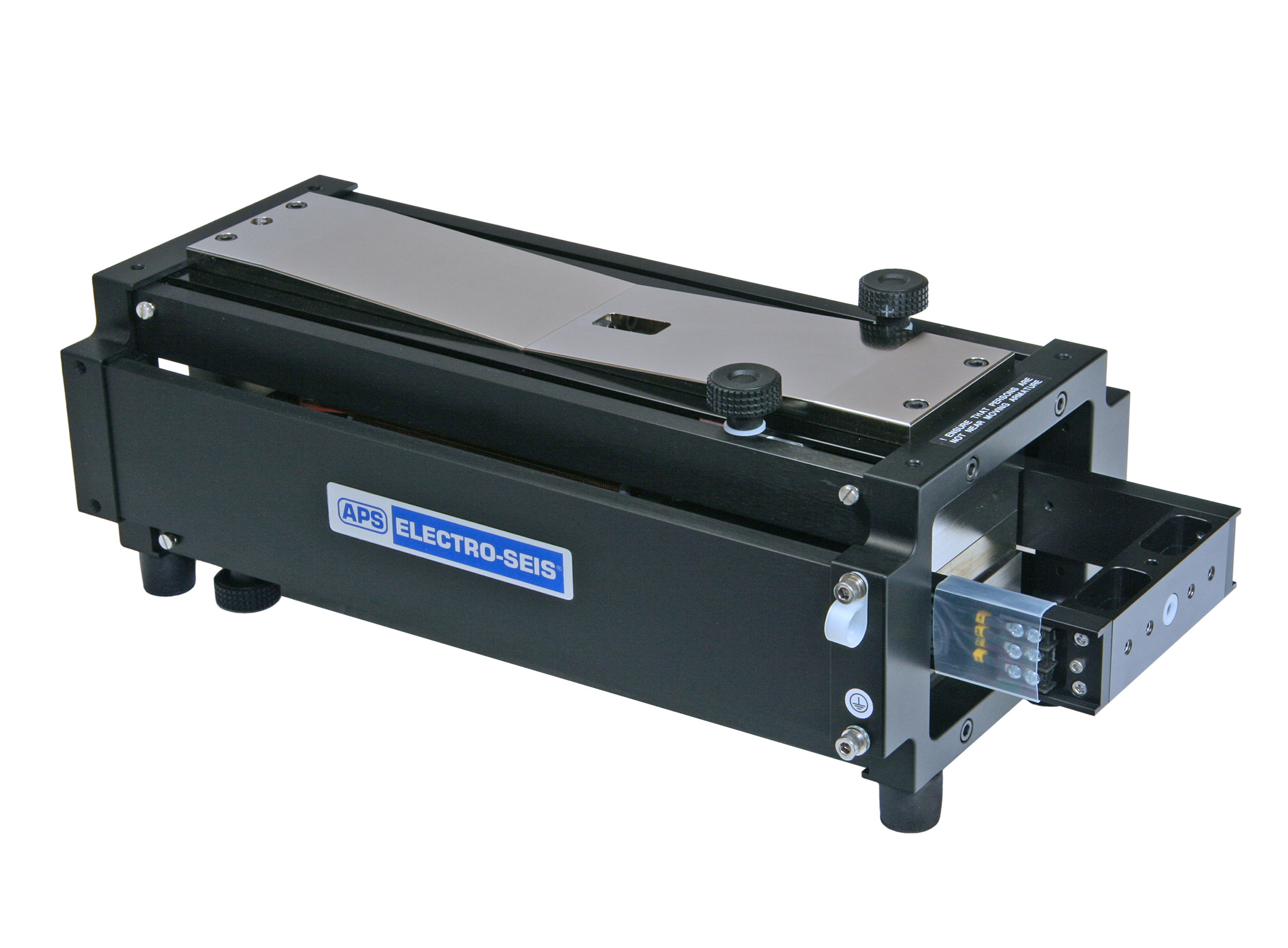

Product details
- Force, max.: 133 N (optionally 186 N)
- Displacement: 158 mm (peak-peak)
- Frequency range: DC…200 Hz
- Payload, max.: horizontal = 25 kg (55 lbs) / vertical = 8 kg (18 lbs)
- horizontal or vertical excitation
- Optional accessories:
- Power amplifier
- Auxiliary table kit − horizontal and vertical
- Handles and bars
- Reaction mass assembly
- Modal stinger kit
- Steel cable kit
- Overtravel switch
For detailed information see current data sheet. Subject to change without notice.
Modes of Operation
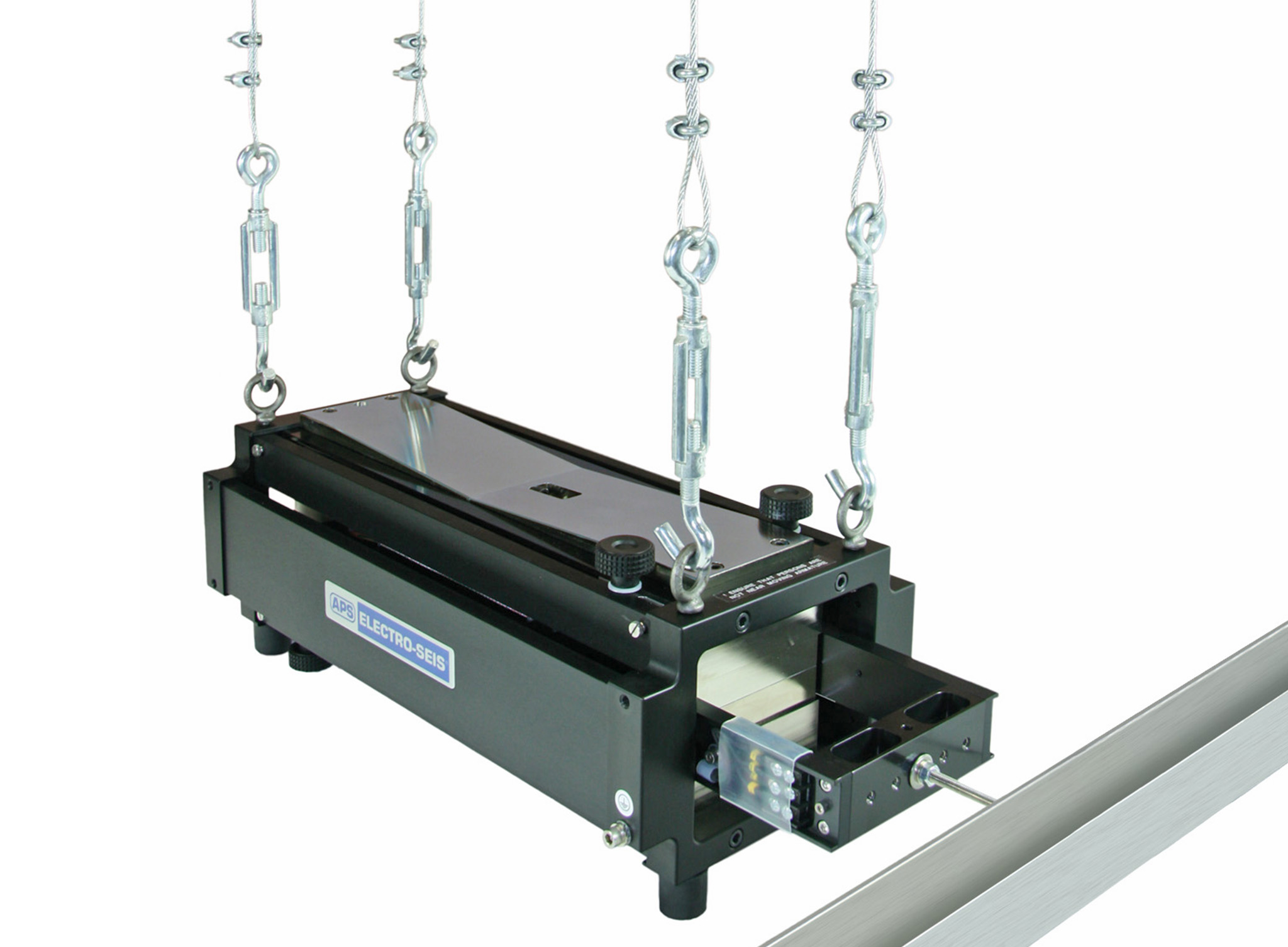
Free Body Mode
Key Features
- Suitable if the test object is in high altitude
- Accelerated shaker body inserts reaction force in the test structure
- Measurement of inserted force by a force transducer or the acceleration of the shaker body
The desired force input points on many test structures lie at a considerable distance above ground level. For tests on such items, it becomes difficult and expensive to use Fixed Body Mode support structures. For such applications, the Free Body Mode can be employed. In this mode the shaker body is used as the reaction mass by suspending the shaker from an overhead support. Besides using a force transducer a very convenient measure of the load force is the axial acceleration of the shaker body. This allows simplification of the test system instrumentation, in that force can be measured with an accelerometer system which is identical to that used to measure the structural response.
Fixed Body Mode
Key Features
- (Generated) shaker force applied directly to structure
- Low influence on structure due to low armature mass
- Measurement of delivered force by force transducer or shaker current
In the Fixed Body Mode, the shaker body is fixed and the armature is attached to the test structure. So shaker force is delivered directly in the test structure. In this mode, force delivered to the test structure can be measured by inserting a force transducer in the thrust linkage between the armature and test structure. Alternatively, with the armature/body suspension bands removed, shaker current can be used as a direct measure of the generated force. The generated force is approximately equal to the force delivered to a resonant test structure, because the armature mass is typically small compared to the modal mass of most large test structures.

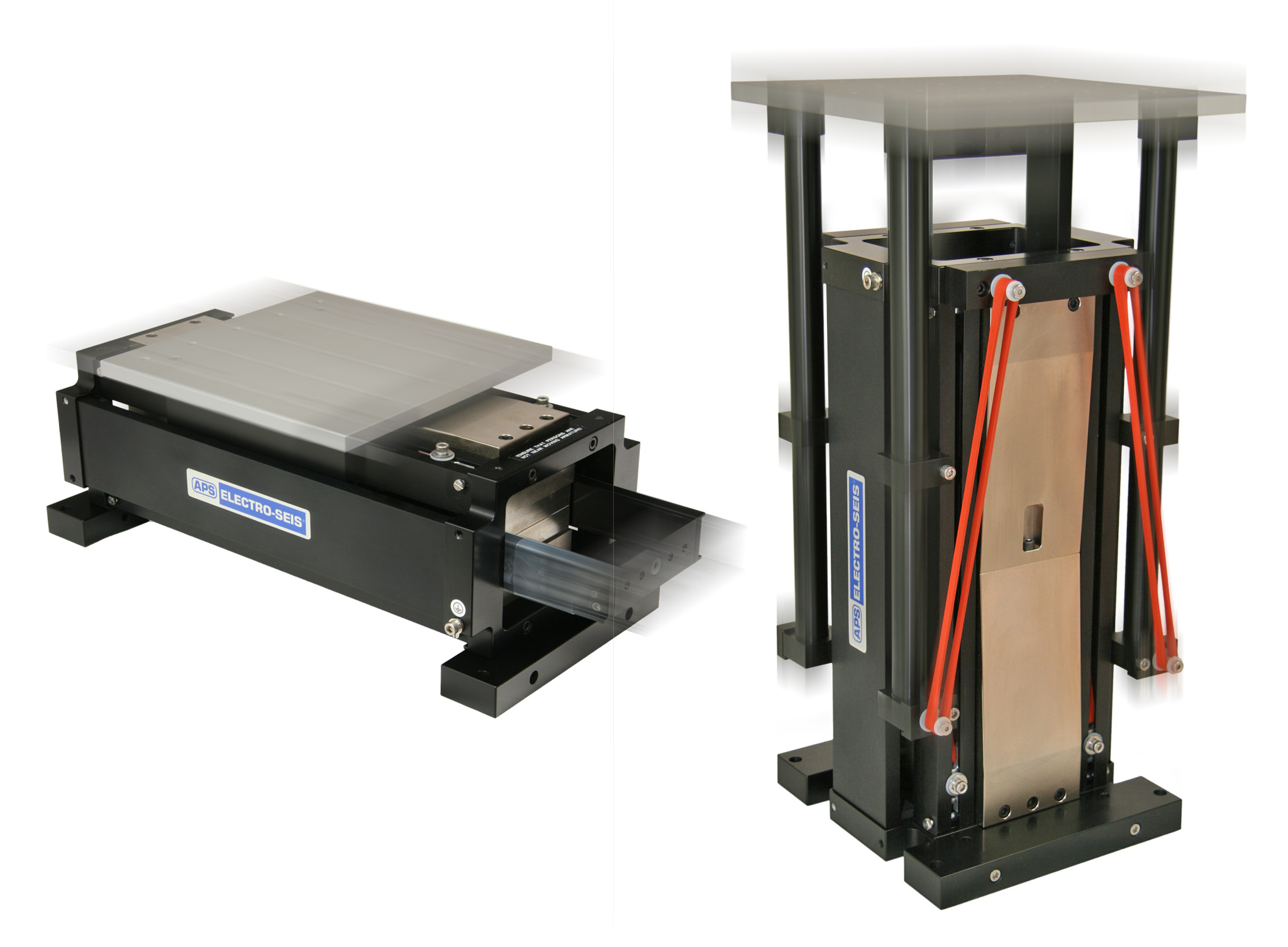
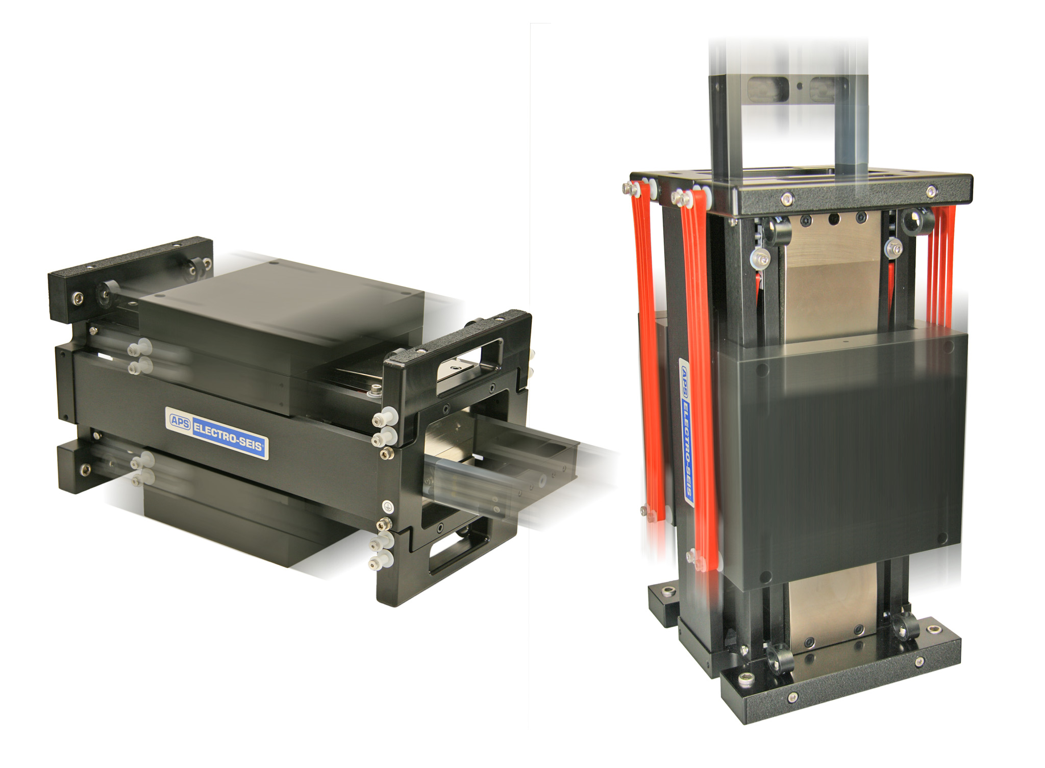
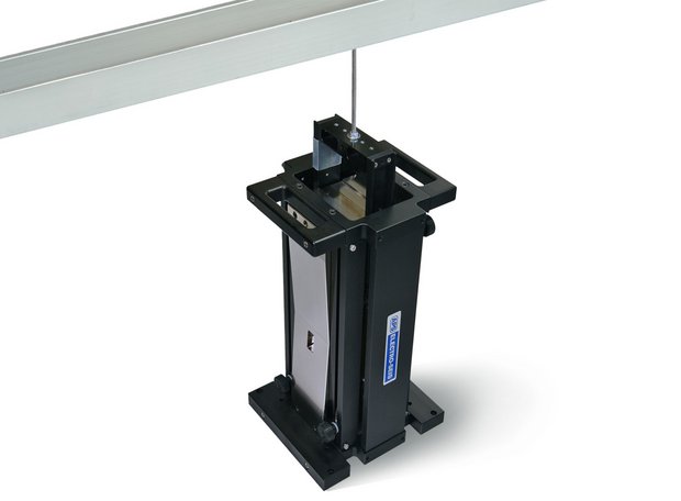
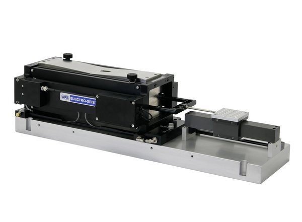
Shaker Table Mode
Key Features
- Horizontal and vertical long stroke tables
- Rugged design for harsh environment
- High payload – up to 20 kg
Auxiliary table accessory units for both horizontal and vertical use employ the high load capability of the APS 113 armature guidance and suspension systems to provide long stroke tables for excitation of test loads. Each auxiliary table has a pattern of threads with helical inserts to mount the test load directly or a fi xture on the table. The mechanical input impedance at the base of a test load that is resonant in the operating frequency range can vary
signifi cantly. Thus, the acceleration response of the table and test item base will exhibit the familiar „peaks“ and „notches“ as frequency is varied. So it is recommended to observe the response of the structure using accelerometers.

Reaction Mass Mode
Key Features
- Inertial vibration exciter
- Vertical or horizontal operation
- Easy to install reaction mass
Many large test structures having horizontal surfaces such as fl oors require vertical or horizontal force applied to these surfaces to generate resonant modes of vibration. The APS shakers may be used in a vertical or horizontal Free Armature Mode by resting the shaker body on the horizontal surface. The moving armature provides a reaction mass that allows for delivery of the shaker force via the shaker body to the surface (inertial shaker). Below a certain cross-frequency the shaker stroke limits the acceleration of the armature and thus the maximum force. Additional masses, e.g. APS 0112 or 4001, lower this frequency. The force applied to the structure can be measured by a force transducer or by measuring the acceleration of the moving masses.
Performance
Eine Anwendung des APS 113 ELECTRO-SEIS® Shakers ist die Bestimmung der dynamischen Eigenschaften von mechanischen Strukturen. Bei Resonanz ist eine große Menge an Energie in der Struktur enthalten, und der Shaker muss die daraus resultierende Bewegung auffangen. Er muss jedoch nur die tatsächliche mechanische Leistung liefern, die durch Dämpfungsmechanismen innerhalb der Struktur dissipiert wird.
Wenn ein Antriebspunkt an einer Struktur in Resonanz mit einer Geschwindigkeit von 1.000 mm/s Spitze schwingt und eine Kraft von 133 N Spitze erforderlich ist, um das Schwingungsniveau aufrechtzuerhalten, liefert der Shaker etwa 65 W RMS an die Struktur.
Eine solche Belastung des Shakers wird als angepasste Resonanzlast bezeichnet und ist rein resistiv, da die Kraft in Phase mit der Geschwindigkeit ist. Eine solche Belastung des Schwingungserregers wird als angepasste Resonanzlast bezeichnet und ist rein ohmsch, da die Kraft in Phase mit der Geschwindigkeit ist.
Wenn die Resonanzlast nicht 133 N × 1.000 mm/s beträgt, können nicht die gesamten 65 W mechanische Leistung an die Struktur abgegeben werden, da das System entweder kraft- oder geschwindigkeitsbegrenzt ist. Wenn der resultierende maximale Antwortpegel nicht groß genug ist, hat der Benutzer die Möglichkeit, den Shaker an einen Antriebspunkt mit einer Impedanz zu verschieben, die näher am angepassten Wert liegt, oder weitere Shaker zum Array hinzuzufügen, das die Struktur antreibt.
Innerhalb der Grenzen der maximalen Kraft und Geschwindigkeit ist die tatsächlich an eine Struktur abgegebene Leistung eine Funktion der mechanischen Eingangsimpedanz am Antriebspunkt.
Bei typischen Modaltests variiert diese Eingangsimpedanz stark in ihrer Größe und ihrem Phasenwinkel. Bei unterschiedlichen Frequenzen kann die Eingangsimpedanz des Antriebspunkts überwiegend federartig,
massenartig oder widerstandsartig erscheinen. Da das Ziel der Tests darin besteht, Resonanzmodi zu ermitteln, bei denen die mechanische Eingangsimpedanz aller Antriebspunkte ohmsch ist, ist die maximale Leistungsfähigkeit des Shakers am aussagekräftigsten in Bezug auf die Kraft und Geschwindigkeit angegeben, die beim Antrieb
einer angepassten ohmschen Last erzielt werden können. Daher wird die Leistung in Form von Grafiken dargestellt, die die Hüllkurven der maximalen Kraft und Geschwindigkeit zeigen, die auf eine Resonanzstruktur als Funktionen der Resonanzfrequenz der Struktur ausgeübt werden.
Eine weitere Anwendung ist die Anregung zur Sensorkalibrierung. Die Beschleunigungsleistung des APS 113 ELECTRO-SEIS®-Shakers mit verschiedenen Massenlasten ist in den nebenstehenden Grafiken dargestellt.


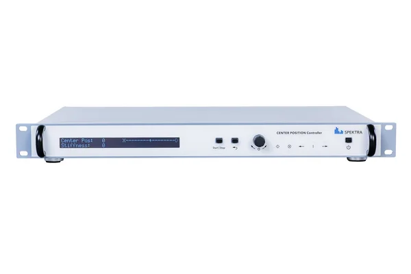
SPEKTRA CPC
The SPEKTRA CPC automatically controls the zero position of a vibration exciter irrespective of its load.
It is essential to employ a CPC-type controller especially when working with an air-bearing vibration shaker without any integrated automatic load compensation.
APPLICATIONS
What are the SPEKTRA areas of application?
Learn more …
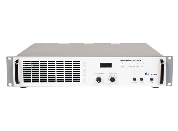
PA 500 DM
The PA 500 DM offers a max. frequency range DC...200 kHz, small harmonic distortion, excellent stability even with temperature or supply line variations and helpful protection functions.
For all vibration exciters that require a 500 VA power amplifier (load impedance 4 Ω).
APPLICATIONS
What are the SPEKTRA areas of application?
Learn more …

APS Auxiliary Table Kits
horizontal and vertical set-up possible
suitable for modal shakers APS 113, APS 400 & APS 420
APPLICATIONS
What are the SPEKTRA areas of application?
Learn more …

APS Reaction Mass
suitable to improve performance of several APS Shakers
for modal shakers
APPLICATIONS
What are the SPEKTRA areas of application?
Learn more …
Similar products
SE-16
Rugged vibration exciter, specially developed for high frequency excitation of small components and sensors (longitudinal and transverse direction).
Devices under test (DUT) can be glued to the top or sides of the technical ceramic armature in any orientation to the main vibration axis.
APPLICATIONS
What are the SPEKTRA areas of application?
Learn more …
SE-20
Innovative spring-guided vibration exciter with leading technology as part of the SE-2X exciter series.
The SE-20 offers a very wide frequency range, low transverse motion, wide temperature range and high payload. In addition to top quality components, the focus is on a versatile range of application and easy implementation in existing test environments.
APPLICATIONS
What are the SPEKTRA areas of application?
Learn more …
SE-21
Powerful high-frequency exciter as part of the SE-2X series with cube-shaped ceramic armature for excitation of all DUT axes.
With its electrodynamic drive system, the SE-21 offers a very wide frequency range with low transverse motions. A high payload, simple operation in a climatic chamber (as SE-21T) and the many extensions enable the SE-21 to be used as a multi-tool for testing, characterizing and calibrating vibration sensors or smaller electronic devices.
APPLICATIONS
What are the SPEKTRA areas of application?
Learn more …
SE-29
Innovative exciter with efficient electrodynamic drive as part of the SE-2X exciter series.
The SE-29 offers a very wide frequency range and low transverse motion. Thanks to the wide temperature range and the high payload, it is optimally suited for larger sensors or geophones. Besides high quality components, the focus lays on a versatile field of application and easy implementation into existing test environments.
APPLICATIONS
What are the SPEKTRA areas of application?
Learn more …
SE-09
Ideal for calibration laboratories, NMI (national metrology institutes) und MEMS tests – in frequencies up to 50 kHz and for devices up to 350 g. The SE-09 high-frequency vibration exciter with air bearings, specifically designed to meet the requirements of calibration laboratories and metrology institutes, as well as for the characterization of MEMS sensors.
APPLICATIONS
What are the SPEKTRA areas of application?
Learn more…
SE-13
Air-bearing electrodynamic Vibration Exciter with mounting table for high payloads up to 50 kg. Especially developed for seismic simulation of components.
Primary and secondary calibration as well as testing of big and heavy low frequency seismic sensors or geophones.
APPLICATIONS
What are the SPEKTRA areas of application?
Learn more …

SE-14
Spring-guided vibration exciter - suitable for daily use in the calibration laboratory as well as for vibration tests in a wide frequency range of 0 Hz…8 kHz.
APPLICATIONS
What are the SPEKTRA areas of application?
Learn more …
APS 113-AB
ELECTRO-SEIS® long stroke vibration exciter, especially developed for the calibration and testing for low frequency sensors and sensor charcterization.
APPLICATIONS
What are the SPEKTRA areas of application?
Learn more …

APS 129
ELECTRO-SEIS® vibration exciter with mounting table for high payloads up to 23 kg and frequencies up to 200 Hz.
Especially developed for the calibration and testing of big and heavy low frequency sensors as well as for sensor characterization (e.g. geophones or heavy seismic sensors).
APPLICATIONS
What are the SPEKTRA areas of application?
Learn more …
APS 500
ELECTRO-SEIS® vibration exciter with mounting table for payloads up to 3 kg and frequencies up to 200 Hz.
Especially developed for the calibration and testing of compact low frequency sensors and for sensor characterization at higher acceleration.
APPLICATIONS
What are the SPEKTRA areas of application?
Learn more …

APS 600
ELECTRO-SEIS® Long Stroke vibration exciter with mounting table for very high payloads up to 25 kg.
Especially developed for the calibration and testing of geophones and heavy seismic sensors.
APPLICATIONS
What are the SPEKTRA areas of application?
Learn more …

APS 113
ELECTRO-SEIS® modal shaker specifically designed to be used alone or in arrays for modal excitation of complex structures, particularly at low frequencies.
Different operating modes with reaction masses, fixing points or auxiliary table kits multiply the application possibilities.
APPLICATIONS
What are the SPEKTRA areas of application?
Learn more …

APS 400
ELECTRO-SEIS® modal shaker with 445 N max. force - suitable for excitation of large structures such as ceilings or bridges
APPLICATIONS
What are the SPEKTRA areas of application?
Learn more …
APS 420
Our strongest ELECTRO-SEIS® modal shaker - maximum force of 900 N and up to 150 mm stroke
The APS 420 is used for vibration tests of airplanes and large structures. Its maximum force of 900 N and up to 150 mm stroke of the shaker unlocks new performance levels.
APPLICATIONS
What are the SPEKTRA areas of application?
Learn more…